Understanding Finite Element Analysis (FEA): A Comprehensive Guide
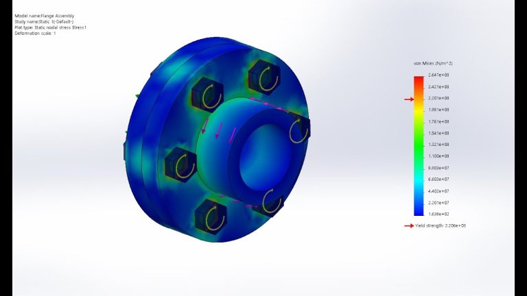
Finite Element Analysis (FEA) is a powerful computational modeling technique widely used in engineering to simulate and analyze the physical behavior of materials and structures under various environmental conditions. This method helps predict how products will react to real-world forces such as vibration, heat, fluid flow, and other physical effects. Below, we delve into the history, fundamental principles, and applications of FEA, providing insights into its critical role in modern engineering and product development.
FEA History | Finite Element Analysis
Finite Element Analysis (FEA) originated in the 1940s and was developed primarily for addressing structural mechanics problems in civil and aerospace engineering. The method has since been adopted across various engineering disciplines, including automotive, biomedical, and consumer products, due to its versatility and accuracy in predicting how complex designs will behave under various types of loads and forces.
Key Milestones in FEA Development:
- 1943: Richard Courant first utilized the Ritz method of numerical analysis and minimization of variational calculus to obtain approximate solutions for vibration systems.
- 1956: Turner, Clough, Martin, and Topp’s paper on the stiffness and deflection of complex structures introduced the term “finite elements.”
- 1970s: The commercial availability of FEA software began, which significantly expanded its use in the engineering industry.
The Intriguing World of Stress-Strain Relationships
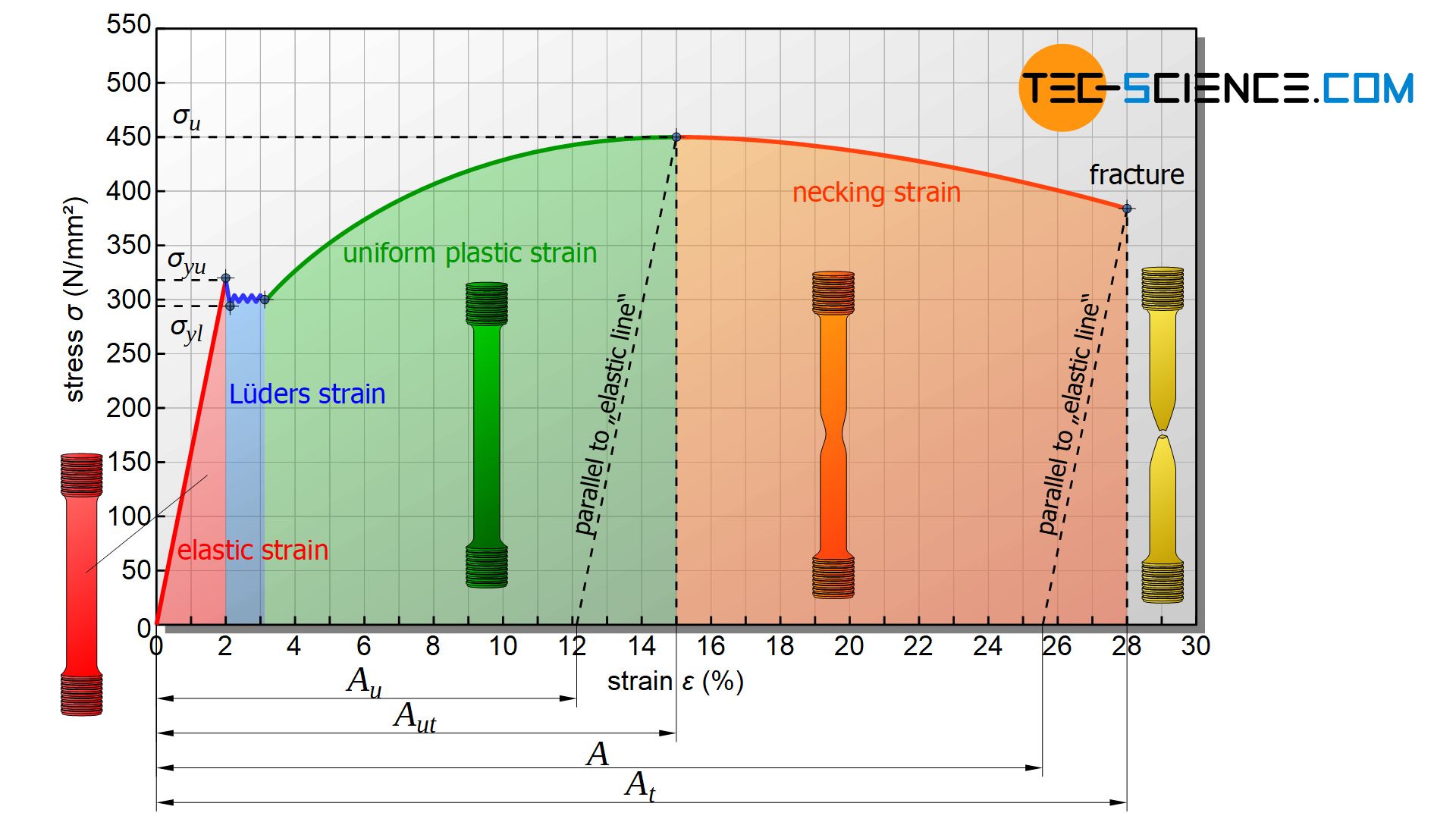
Understanding the stress-strain relationship is crucial for predicting material behavior under external forces. Stress refers to the internal forces in a material (force per unit area), while strain refers to the deformation or displacement that occurs as a result of stress.
Types of Stress:
- Normal Stress: Acts perpendicular to the surface (tensile or compressive).
- Shear Stress: Acts parallel to the surface.
Types of Strain:
- Elastic Strain: Temporary deformation where the material returns to its original shape after the stress is removed.
- Plastic Strain: Permanent deformation that occurs when the material is stretched beyond its elastic limit.
- Luders Strain: Localized deformation that appears as distinct bands in some metals, marking the onset of plasticity under stress.
- Uniform Plastic Strain: Evenly distributed deformation across a material that occurs after yielding and before the initiation of necking.
- Necking Strain: Concentrated deformation that results in a significant reduction in cross-sectional area of the material, often leading to fracture under continued stress.
- Fracture: The breaking or cracking of a material, typically following significant deformation or necking, ultimately leading to complete separation into parts.
Understanding Partial Differential Equations (PDEs) in Finite Element Analysis (FEA)
Before diving into the application of Finite Element Analysis (FEA), it is crucial to grasp the various types of Partial Differential Equations (PDEs) and their relevance to FEA. This knowledge is essential for anyone using FEA, emphasizing that the effectiveness of FEA software hinges on the user’s proficiency.
PDEs are typically classified into three main categories, each with distinct characteristics and applications:
- Elliptic PDEs: These equations are known for their smooth solutions and are often used in problems where equilibrium states are analyzed. A common example is the Poisson equation.
- Hyperbolic PDEs: Characterized by their ability to model phenomena with sharp discontinuities or wave-like behaviors, such as sound or shock waves. The Wave equation is a typical example of a hyperbolic PDE.
- Parabolic PDEs: These are used primarily for problems involving time-dependent processes, such as heat diffusion or chemical concentration diffusion. The Heat equation, following Fourier’s law, is an example of a parabolic PDE.
To solve these PDEs using FEA, it is essential to define appropriate boundary and/or initial conditions. The specific conditions required depend on the type of PDE being addressed. Understanding the nature of each PDE category helps in setting up these conditions correctly and interpreting the results effectively.
In summary, recognizing the type of PDE involved in your analysis is fundamental in leveraging the full potential of FEA, ensuring that the simulations are both accurate and reliable.
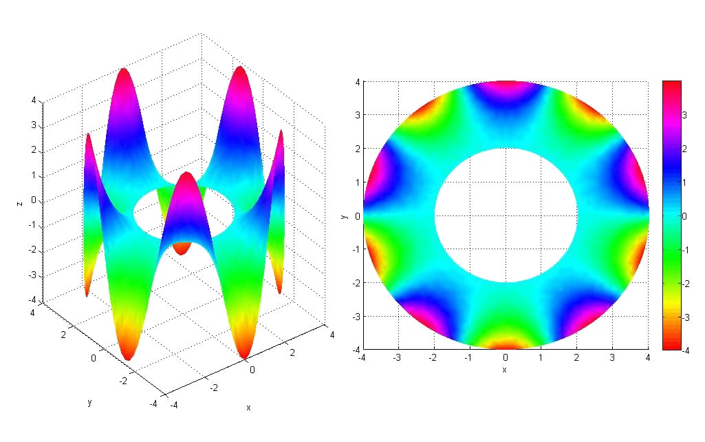
Mesh Quality and Refinement
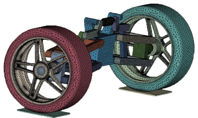
The quality of the mesh significantly influences the accuracy of an FEA simulation. A finer mesh generally provides more accurate results but requires more computational resources.
Mesh Errors and Independence Studies
To ensure the reliability of simulation results, engineers perform mesh independence studies, which involve running the simulation at different mesh densities and ensuring that increasing the mesh density further does not significantly change the results.
Mesh Convergence
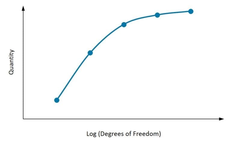
Mesh convergence refers to the process of refining the mesh used in FEA simulations until the solution (such as stress, strain, displacement, etc.) changes very little with further mesh refinement. This concept is based on the principle that smaller finite elements generally provide more accurate results. However, simply reducing the element size increases computational cost and time, making it essential to find a balance.
Importance of Mesh Convergence
- Accuracy: Without proper convergence testing, the accuracy of the simulation results can be questionable. Mesh convergence ensures that the results are independent of the mesh size, leading to more reliable outcomes.
- Efficiency: Understanding when the mesh has converged helps in optimizing the number of elements used, which can significantly reduce computational resources and time.
- Validation: Mesh convergence is a part of the validation process for any simulation. It provides a check that the mathematical model and the numerical solution are correctly implemented.
Steps to Achieve Mesh Convergence
- Initial Meshing: Start with an initial mesh that is neither too coarse nor too fine. It should be reasonably sized based on the geometry and expected regions of interest (e.g., areas with high stress concentrations).
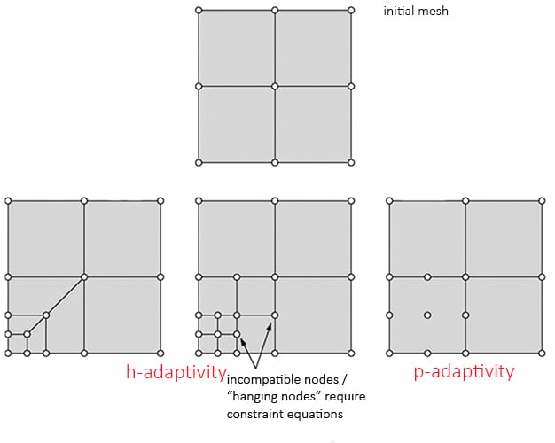
- Refinement Strategy: Implement a refinement strategy where the mesh is systematically refined in several steps. This could be global refinement or targeted local refinement in areas where the solution gradients are high.
- Convergence Criteria: Define convergence criteria before starting the refinement process. This could be based on changes in key quantities of interest like maximum stress or displacement. A common criterion is that changes should be less than a certain percentage (e.g., 1% or 5%).
- Iterative Testing: After each refinement, re-run the simulation and compare the results with the previous mesh. Continue refining until the convergence criteria are met.
- Documentation: Document each step of the convergence test, including the mesh sizes, element types, and results. This documentation is crucial for validating the simulation process and for future reference.
- Software Tools: Utilize meshing tools and software features that assist in mesh refinement and convergence analysis. Many FEA software packages have built-in tools to automate part of this process.
Common Challenges in Mesh Convergence
- Computational Cost: Finer meshes significantly increase the number of calculations, which can escalate computational costs and time requirements.
- Complex Geometries: In models with complex geometries, achieving uniform mesh refinement can be challenging and may require sophisticated meshing algorithms or manual intervention.
- Stress Singularities: Areas near stress singularities (e.g., sharp corners, points of load application) can be particularly challenging for mesh convergence.
- Non-linear Materials/Loads: Non-linearities in material properties or loading conditions can complicate the convergence behavior, requiring more sophisticated approaches and careful interpretation of results.
Applications of Finite Element Analysis
FEA has a wide range of applications in various engineering fields, each demonstrating the adaptability and depth of this analysis method. Here are some expanded examples:
Dynamic Analysis
Dynamic analysis involves examining how structures respond to time-varying loads, which can include impacts, vibrations, and other dynamic forces:
- Automotive Crash Simulation: Automotive engineers use FEA to simulate vehicle responses during crashes to improve safety features, such as crumple zones and the integrity of safety cages.
- Earthquake Engineering: Structural engineers use dynamic analysis to predict how buildings and bridges will react during earthquakes, helping to design structures that can withstand seismic forces.
Heat Transfer
FEA is essential for analyzing thermal properties and behaviors in various systems, ensuring that devices operate safely under thermal loads:
- Electronics Cooling: Engineers use FEA to design cooling strategies for electronic components, such as CPUs and GPUs, which generate significant amounts of heat that must be dissipated to prevent failure.
- Turbine Blade Temperature Distribution: In aerospace, FEA is used to model the heat distribution and cooling flows in turbine blades, ensuring they can withstand high temperatures during operation.
Fluid-Structure Interaction (FSI)
FSI is a critical application of FEA where the interaction of fluid and solid structures is analyzed, important in several key industries:
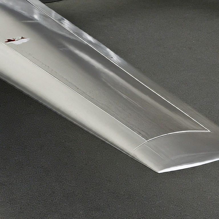
- Aerospace and Defense: Analyzing the impact of air currents on aircraft wings or missile bodies to ensure optimal performance and stability.
- Civil Engineering: Studying the effect of water flow on dam structures or the impact of wind on skyscrapers and large bridges.
Acoustic Simulation
FEA helps in predicting and analyzing the acoustic behavior of products, which is vital in several areas:
- Automotive Acoustics: Designing quieter cabins by analyzing how sound waves interact with car components.
- Building Acoustics: Ensuring sound insulation and acoustics are optimal in building designs, important in theaters and concert halls.
Biomedical Applications
FEA is increasingly used in the biomedical field to simulate and analyze biological systems and devices:
- Implant Design: Simulating the performance of biomedical implants, such as hip replacements and stents, under realistic physiological conditions to ensure they can withstand bodily forces.
- Bone Mechanics: Studying stress and strain in human bones under various conditions to aid in the design of medical treatments including surgical interventions.
Manufacturing Processes
FEA plays a critical role in optimizing manufacturing processes by predicting the outcomes of process changes:
- Forging and Stamping: Analyzing metal deformation during forging and stamping processes to predict defects and ensure uniformity.
- Injection Molding: Simulating plastic flow in molds to identify and eliminate potential issues with air pockets or incomplete filling.
Each of these applications demonstrates how FEA helps engineers and researchers address complex problems by providing insights into the physical behaviors of materials and structures under various conditions. This capability is crucial across all domains of engineering, making FEA an indispensable tool in modern design and analysis processes.


FEA Tools and Software
Modern FEA tools integrate sophisticated algorithms that can handle complex simulation scenarios. Below are some of the most popular FEA software tools, each known for specific capabilities and strengths:
- ANSYS: Known for its advanced capabilities and extensive material models, ANSYS is widely used across industries for complex simulations. It supports a broad range of analyses including structural, thermal, and fluid dynamics.
- Abaqus: Offers powerful and comprehensive solutions for both routine and sophisticated engineering problems. Abaqus is particularly strong in nonlinear simulations and can handle challenging material behaviors and complex contact conditions.
- SolidWorks Simulation: Integrates seamlessly with SolidWorks CAD software, making it a popular choice for product designers. It provides a user-friendly environment for conducting basic to complex simulations within the familiar SolidWorks interface.
- Autodesk Nastran: Inherits the robustness of the Nastran solver, which is well-regarded in the aerospace and automotive industries. Autodesk Nastran offers advanced analysis capabilities including dynamic response, heat transfer, and fatigue analysis.
- COMSOL Multiphysics: Renowned for its ability to handle multiphysics problems where simultaneous solutions to multiple physical models are required. COMSOL is particularly useful in research and development for simulating real-world scenarios across physics disciplines.
- NX Nastran: Developed by Siemens, NX Nastran is a premier FEA tool used for solving complex engineering problems. It is widely utilized in aerospace, automotive, electronics, heavy machinery, and other industries for structural, thermal, and vibrational analyses.
- MSC Marc: Known for its ability to simulate non-linear and complex contact behavior. MSC Marc is often used for manufacturing process simulations like forging and extrusion as well as for solving complex material behavior like elastomer, rubber, and foam.
- LS-DYNA: Particularly favored for dynamic and complex real-world simulations. LS-DYNA is extensively used in the automobile industry for crash testing, as well as for analyzing explosions and other high-performance simulations that require the detailed modeling of transient dynamic phenomena.
Each of these tools offers specific advantages and features that cater to different types of engineering needs. Choosing the right FEA software often depends on the specific requirements of the project, including the types of analyses, industry standards, and the preferred workflow of the engineering team.
