Understanding Computational Fluid Dynamics (CFD): A Comprehensive Guide
Computational Fluid Dynamics (CFD) is a powerful tool that allows engineers and designers to mathematically simulate and analyze fluid flow, heat transfer, and other related phenomena using computer-based numerical methods. By solving complex governing equations, such as the Navier-Stokes equations, CFD software can accurately predict the behavior of fluids in various scenarios, enabling engineers to optimize their designs and improve product performance.
In the world of engineering, CFD has become an essential tool for evaluating the aerodynamic performance of products, such as race cars, aircraft, and wind turbines. Traditionally, engineers relied on physical testing of prototypes to assess and optimize their designs. However, with the rapid advancement of computational power and the development of sophisticated CFD software, engineers can now simulate and analyze fluid flow, heat transfer, and other physical properties in a virtual environment.
CFD simulations take into account various physical properties of fluids, including velocity, pressure, viscosity, density, and temperature. These properties are calculated simultaneously based on the defined operating conditions and boundary conditions, ensuring accurate and realistic results. By considering these factors, CFD enables engineers to gain valuable insights into the performance of their designs without the need for costly and time-consuming physical testing.
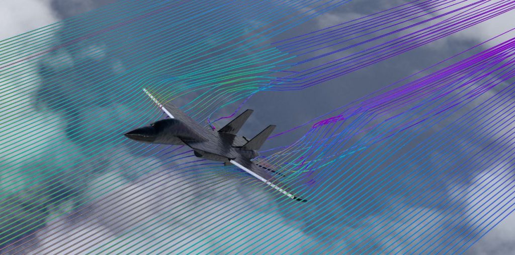
The accuracy of CFD simulations depends on several factors, including the proper selection of governing equations, numerical methods, and physics models. The most commonly used governing equations in CFD are the Navier-Stokes equations, which can be modified to account for additional phenomena such as heat transfer, phase change, or chemical reactions. Choosing the appropriate numerical methods and physics models is crucial for obtaining reliable and accurate results.
When applied correctly, CFD can provide engineers with quick and valuable performance insights, allowing them to iterate and optimize their designs more efficiently. This ultimately leads to the development of better-performing, more efficient, and cost-effective products across various industries, including aerospace, automotive, and renewable energy.
CFD simulations unlock unprecedented insights into fluid dynamics, empowering engineers to optimize designs, enhance performance, and drive innovation across industries.
In summary, Computational Fluid Dynamics (CFD) is a powerful simulation tool that enables engineers to analyze and predict fluid flow, heat transfer, and related phenomena using computer-based numerical methods. By leveraging CFD, engineers can optimize their designs, improve product performance, and reduce the need for costly physical testing, ultimately leading to the development of more efficient and effective solutions.
CFD History | Computational Fluid Dynamics
Computational Fluid Dynamics (CFD) emerged as a powerful tool, but its progress was tied to the evolution of computing power. Let’s explore the key milestones in the history of CFD
Early Days (Before 1910): The focus was on building the theoretical foundations – refining mathematical models and numerical methods to describe fluid flow. However, the complexity of these calculations limited practical applications.
Hand Calculations and Early Computers (1910-1950): Researchers began applying the developed models and methods to solve fluid flow problems, initially relying on tedious hand calculations. The advent of early computers like ENIAC marked a turning point, enabling more complex simulations.
Computer-Based Modeling Takes Off (1950-1960): This era saw the pioneering use of computers to model fluid flow based on the fundamental Navier-Stokes equations. Researchers explored different methods and achieved the first simulations of 2D, transient, incompressible flow.
3D Simulations and Commercial Codes (1960-1970): The publication of the first scientific paper on 3D computational analysis of bodies marked a significant advancement. Commercial CFD codes started to emerge, and important methods like the k-ε turbulence model were developed, laying the groundwork for future applications.
CFD Takes Flight (1970-1980): Leading organizations like Boeing and NASA developed their own CFD codes, applying them to analyze and design various vehicles, including submarines, ships, cars, helicopters, and aircraft.
Accuracy and Adoption (1980-1990): Researchers achieved more accurate solutions for complex flow problems, particularly in the area of transonic flows. Commercial CFD software gained traction in both academia and industry, expanding the reach and impact of this technology.
CFD Everywhere (1990-Present): The continuous advancements in computing power and software have led to the widespread adoption of CFD across virtually every sector. Today, CFD plays a crucial role in numerous fields, from aerospace and automotive design to weather prediction and medical research.
The Curious Case of the Navier-Stokes Equations
At the heart of fluid dynamics lies a set of equations known as the Navier-Stokes equations. These equations mathematically describe the movement of fluids, forming the foundation for theoretical models in this field. However, the story behind their development is quite unique.
The equations bear the names of two individuals, Claude-Louis Navier and Sir George Gabriel Stokes, who, interestingly, never crossed paths. Navier initiated the work, conducting studies on a portion of the equations until 1822. Several years later, in 1845, Stokes independently picked up where Navier left off, refining and completing the set of equations we recognize today.

© Simscale
Governing Equations of CFD
In the field of thermo-fluids analysis, the governing equations that dictate the behavior of fluids are based on the conservation laws of physical properties. These fundamental equations, known as the three laws of conservation, form the backbone of computational fluid dynamics (CFD) simulations and are essential for accurately predicting fluid flow and heat transfer.
The three conservation laws are:
- Conservation of Mass: Continuity Equation
- Conservation of Momentum: Newton’s Second Law
- Conservation of Energy: First Law of Thermodynamics or Energy Equation
These laws state that within a closed system, mass, momentum, and energy remain constant, ensuring that everything is conserved. To conduct a comprehensive thermo-fluids analysis, engineers and researchers must simultaneously solve for three key variables: velocity (v⃗), pressure (p), and temperature (T). Pressure and temperature are considered the two essential independent thermodynamic variables.
In addition to velocity, pressure, and temperature, the final form of the conservation equations incorporates four other thermodynamic variables: density (ρ), enthalpy (h), viscosity (μ), and thermal conductivity (k). These properties, with viscosity and thermal conductivity also being transport properties, are uniquely determined by the values of pressure and temperature.
To gain a complete understanding of fluid flow, it is necessary to analyze velocity, pressure, and temperature at every point within the flow regime. Furthermore, the method used to observe fluid flow based on kinematic properties is a crucial consideration. There are two primary approaches to investigating fluid motion: Lagrangian and Eulerian.
- The Lagrangian description of fluid motion involves tracking individual fluid particles that are large enough to detect properties. This method requires examining the initial coordinates of a particle at time t0 and the coordinates of the same particle at time t1. However, following millions of separate particles throughout their paths is practically impossible.
- In contrast, the Eulerian method focuses on examining the velocity field as a function of space and time, rather than tracking specific particles across their paths. This approach is more practical and widely used in CFD simulations.
By leveraging the power of the conservation laws and the appropriate methods for analyzing fluid flow, engineers and researchers can accurately predict the behavior of fluids in various applications, from aerodynamics to heat transfer. Through the use of advanced CFD software and numerical methods, thermo-fluids analysis has become an indispensable tool for optimizing designs, improving efficiency, and driving innovation across industries.
This missile example precisely explains the two methods.

Lagrangian: In this approach, we select individual points at the start of the domain and follow their trajectories until they reach the endpoint.
Eulerian: Here, we define a specific region (Control Volume) within the fluid and examine the flow of particles inside this defined space.
Continuity Equation
The equation for the Conservation of Mass is specified as:
\frac{Dρ}{Dt} +\rho (\nabla \cdot \vec{v}) =0 \tag{1}where ρ is the density, v⃗ the velocity and ∇ the gradient operator.
\vec{\nabla} = \vec{i} \frac{\partial}{\partial x} + \vec{j} \frac{\partial}{\partial y} + \vec{k} \frac{\partial}{\partial z} \tag{2}If the density is constant, the flow is assumed to be incompressible and the continuity equation reduces to:
\frac{D\rho}{Dt} = 0 \rightarrow \nabla \cdot \vec{v} = \frac{\partial u}{\partial x} + \frac{\partial v}{\partial y} + \frac{\partial w}{\partial z} = 0 \tag{3}Navier-Stokes Equation
Conservation of Momentum which can be referred to as the Navier-Stokes Equation is given by:
\overbrace{\frac{\partial}{\partial t} (\rho \vec{v})}^{I} + \overbrace{\nabla \cdot (\rho \vec{v} \vec{v})}^{II}= \overbrace{-\nabla p}^{III} + \overbrace{\nabla \cdot \left(\overline{\overline{\tau}}\right)}^{IV} + \overbrace{\rho \vec{g}}^{V} \tag{4}where p is static pressure, τ¯¯¯¯¯¯ viscous stress tensor and ρg⃗ is the gravitational force per unit volume. Here, the roman numerals denote:
I: Local change with time
II: Momentum convection
III: Surface force
IV: Diffusion term
V: Mass force
If the fluid is assumed to be incompressible with constant viscosity coefficient μ the Navier-Stokes equation simplifies to:
Viscous stress tensor τ¯¯¯¯¯¯ can be specified as below in accordance with Stoke’s Hypothesis:
\tau_{ij} = \mu \frac{\partial v_i}{\partial x_j} + \frac{\partial v_j}{\partial x_i} – \frac{2}{3}(\nabla \cdot \vec{v}) \delta_{ij} \tag{5}If the fluid is assumed to be incompressible with constant viscosity coefficient μ the Navier-Stokes equation simplifies to:
\rho \frac{D\vec{v}}{Dt} = -\nabla p + \mu \nabla^2 \vec{v} + \rho \vec{g} \tag{6}Newton’s First Law of Thermodynamics
Conservation of Energy is the first law of thermodynamics which states that the sum of the work and heat added to the system will result in the increase of the energy in the system:
dE_t=dQ + dW \tag{7}where dQ is the heat added to the system, dW is the work done on the system and dEt is the increment in the total energy of the system. One of the common types of an energy equation is:
\rho \left[\overbrace{\frac{\partial h}{\partial t}}^{I} + \overbrace{\nabla \cdot (h\vec{v})}^{II} \right] = \overbrace{-\frac{\partial p}{\partial t}}^{III} + \overbrace{\nabla \cdot (k\nabla T)}^{IV} + \overbrace{\phi}^{V} \tag{8}I: Local change with time
II: Convective term
III: Pressure work
IV: Heat flux
V: Source term
Partial Differential Equations (PDEs)
The mathematical model provides us with the interrelationships between the transport parameters that are involved in the entire process, either directly or indirectly. Although each term in these equations has a relative impact on the physical phenomenon, changes in parameters should be considered simultaneously through the numerical solution, which includes differential equations, vector, and tensor notations.
A Partial Differential Equation (PDE) contains multiple variables and is denoted by the symbol “∂”. If the equation is derived using “d”, it is called an Ordinary Differential Equation (ODE), which involves a single variable and its derivative. PDEs are used to transform the differential operator (∂) into an algebraic operator to obtain a solution. PDEs are widely employed in various fields, including heat transfer, fluid dynamics, acoustics, electronics, and quantum mechanics, to generate solutions to complex problems.
Example of ODE:
\frac{d^2 x}{dt^2} = x \rightarrow x(t) \quad \text{where T is the single variable} \tag{11}Example of PDE:
\frac{\partial f}{\partial x} + \frac{\partial f}{\partial y} = 5 \rightarrow f(x,y) \quad \text{where both x and y are the variables} \tag{12}What is the significance of PDEs in seeking a solution to governing equations? To answer this question, we initially examine the basic structure of some PDEs to create connotation. For instance:
\frac{\partial^2 f}{\partial x^2} + \frac{\partial^2 f}{\partial y^2} = 0 \rightarrow f(x,y) \rightarrow \text{Laplace Equation} \tag{13}By comparing equation (5) and equation (13), we can identify the Laplace component within the continuity equation. This raises the question: what is the next step, and what does this Laplace analogy signify? To begin solving these complex equations, the subsequent step involves discretization, which initiates the numerical solution process.
Discretization
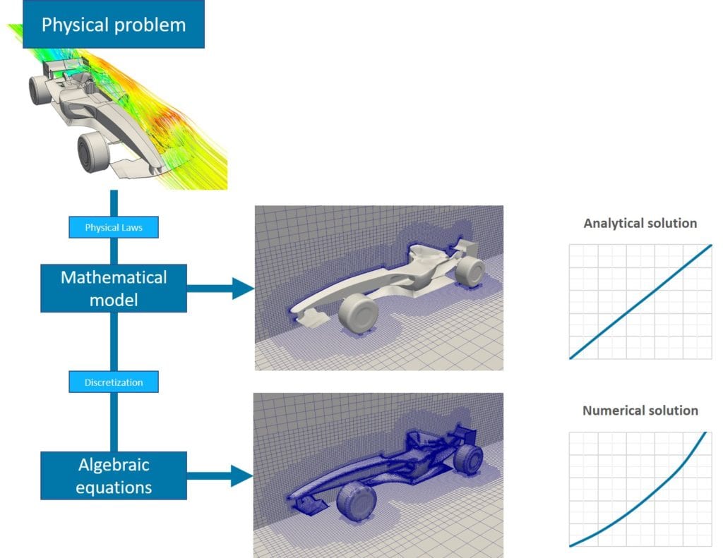
The numerical solution is an approach that relies on discretization to provide approximate solutions for complex problems that cannot be solved using analytical methods. As shown in Figure 4, solution processes that do not involve discretization only yield an analytical solution, which is precise but limited to simple cases.
Furthermore, the accuracy of the numerical solution is significantly influenced by the quality of the discretization process. Some widely employed discretization methods include finite difference, finite volume, finite element, spectral (element) methods, and boundary element methods.
© Simscale
Mesh Convergence
Breaking down complex tasks into smaller, manageable sub-tasks is a proven strategy for achieving goals and avoiding the pitfalls of multitasking, which often leads to procrastination or failure. This approach has been successfully applied in the field of Computational Fluid Dynamics (CFD).
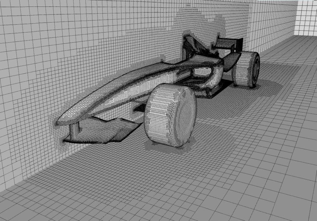
In CFD analysis, the solution domain is divided into multiple sub-domains called cells. The collection of these cells in the computational structure is referred to as a mesh. By segmenting the problem into smaller components, CFD experts can tackle complex fluid flow simulations more effectively and efficiently.
© Simscale
Meshing is a critical step in the discretization process, where the domain is divided into small cells or elements to facilitate the application of the mathematical model. This process is carried out under the assumption of linearity within each cell, which means that the behavior of the variables to be solved can be approximated as linear within the confines of each cell. Consequently, this assumption necessitates the use of a finer mesh in regions where the physical properties being predicted are expected to exhibit highly variable or rapidly changing behavior.
Mesh Errors and Mesh Independence Studies
Mesh-related errors are a prevalent issue that can lead to inaccurate solutions or even complete failure of the simulation. This problem often arises when the mesh is too coarse, and the flow physics are not adequately captured within an area of large, coarse cells. To mitigate this issue, it is essential to conduct a mesh independence study to ensure that the mesh does not significantly impact the solution. A mesh independence study can be outlined as follows:
- Create an initial mesh that accurately represents the geometry and appears to have sufficient cells and mesh density based on visual inspection.
- Refine the mesh by increasing the number of cells and mesh density in areas of interest. Perform the CFD analysis again and compare the results accordingly. For example, if the case involves examining internal flow through a channel, comparing pressure drops at critical regions would be a good indicator of mesh sensitivity.
- Continue refining the mesh until the results and key physical properties (such as pressure drop or maximum velocity) converge satisfactorily with the previous mesh and CFD analysis.
By conducting a mesh independence study, errors stemming from the mesh structure can be eliminated, and the optimal number of elements can be determined to ensure efficient computation. Figure 6 illustrates the change in static pressure at an imaginary region X as the number of mesh elements increases. Based on the information provided in Figure 6, approximately 1,000,000 elements would have been sufficient to conduct a reliable study.
Convergence in Computational Fluid Dynamics
Sculpting is an art form that demands exceptional talent and the ability to envision the final masterpiece from the outset. A sculpture begins as a simple block of stone but can be transformed into a stunning work of art through the artist’s skill and dedication. The process of methodically removing material is essential to achieving the desired final form.
Similarly, Computational Fluid Dynamics (CFD) involves a process that relies on incrementally refining results to arrive at a final solution. In a CFD analysis, an initial guess serves as the starting point, much like the stone block an artist begins with. Through numerical iteration, the solution field evolves from this initial guess into a final, stable flow field. However, it is crucial to remember that while numerical iterations are responsible for reaching a final solution, the accuracy of the result is entirely dependent on the quality of the mesh.
Convergence is a critical concern in computational analysis. The movement of fluids is governed by non-linear mathematical models that incorporate various complex phenomena such as turbulence, phase change, and mass transfer, all of which significantly impact convergence. In contrast to analytical solutions, numerical solutions are obtained through an iterative process in which results are refined by reducing errors between successive stages. The difference between the last two solutions determines the error. As the absolute error decreases, the reliability of the result improves, and the solution converges towards a stable state.
When to know that the solution has converged?
In CFD simulations, the solving process should continue iterating until the solution field reaches a stable state and no longer changes significantly with further iterations. This principle applies to both steady-state and transient simulations.
In steady-state simulations, the iterative process continues until the solution converges to a point where the changes between successive iterations become negligible. At this stage, the solution is considered to have reached a stable state, and the simulation can be concluded.
For transient simulations, which involve time-dependent flow phenomena, convergence must be achieved at each time step. In other words, each time step in a transient simulation is treated as a mini steady-state problem. The iterative process at each time step continues until the solution converges, similar to the process in a steady-state simulation. Only after convergence is achieved at a particular time step can the simulation proceed to the next time step.
Ensuring proper convergence is crucial for obtaining accurate and reliable results in CFD simulations. Monitoring convergence criteria, such as residuals or changes in key variables, helps determine when the solution has reached a stable state. Adequate convergence ensures that the numerical errors introduced by the iterative process are minimized and that the final solution represents a physically meaningful result.
What are the convergence criteria?
Just as a sculptor gradually chips away at a block of stone to reveal the final masterpiece, the residuals of equations in a CFD simulation change with each iteration. As the iterations progress and the residuals decrease to a predetermined threshold value, convergence is achieved. This process is similar to an artist removing the final small pieces of stone to complete a sculpture.
Here are some key points to keep in mind about convergence:
- Convergence can be accelerated by adjusting parameters such as initial conditions, under-relaxation factors, and the Courant number. These parameters help guide the solution towards a stable state more quickly.
- It is important to note that a converged solution does not necessarily guarantee a correct solution. A poor mathematical model or an inadequate mesh can lead to incorrect results, even if the solution has converged. Therefore, it is crucial to ensure that the underlying physics and mesh quality are appropriate for the problem at hand.
- Convergence can be stabilized through various methods, such as maintaining reasonable mesh quality, employing mesh refinement techniques, and using appropriate discretization schemes (ranging from first to second order). These measures help to minimize numerical instabilities and ensure a smooth convergence process.
- To avoid ambiguity and ensure the reliability of the results, it is essential to verify that the solution is repeatable. This means that running the simulation multiple times with the same settings should produce consistent results.
Understanding and properly managing convergence is a critical aspect of CFD simulations. By carefully monitoring residuals, adjusting relevant parameters, and ensuring the quality of the mesh and mathematical model, engineers can obtain accurate and reliable results from their CFD analyses.
Applications of Computational Fluid Dynamics
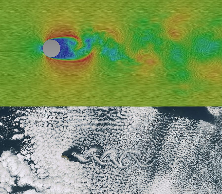
CFD is a versatile tool that can be applied to any situation involving fluid flow. The classic academic example of flow over a cylinder, taught in university-level fluid dynamics courses, has far-reaching applications, including the study of cloud movement in the atmosphere, as illustrated in Figure 7.
This fundamental concept helps students understand basic fluid dynamics principles, such as boundary layer separation, wake formation, and vortex shedding. The same phenomenon can be observed in nature, particularly in the movement of clouds around objects like mountains or tall buildings, creating unique shapes and structures.
CFD simulations can model and analyze these atmospheric flows, as well as numerous other applications across various fields, including aerospace, automotive, civil, and biomedical engineering. The ability to accurately simulate and analyze fluid flow using CFD has revolutionized the way engineers design and optimize products and systems.
Incompressible and Compressible Flow
When compressibility becomes a significant factor, CFD analysis provides robust and accurate solutions for compressible flows. A prime example is the Large Eddy Simulation of flow around a cylinder, which effectively captures the complex fluid dynamics in compressible flow scenarios.
Laminar and Turbulent Flow
Flow can be classified as either laminar or turbulent based on properties such as density, viscosity, and velocity. While most commercial applications involve turbulent flow, there are exceptions, such as the laminar flow of natural convection from a warm light. Turbulent simulations are more computationally demanding due to the additional terms in the governing equations. The flow through a valve is one example of a turbulent flow analysis.
Mass and Thermal Transport
CFD simulations for Mass and Thermal Transport involve analyzing the movement and interaction of fluids, heat, and various substances within a given system. These simulations are crucial for understanding and optimizing processes in fields such as chemical engineering, HVAC, and environmental studies. Here are a few examples of CFD simulations for Mass and Thermal Transport:
- Heat Exchanger Analysis:
- Model the flow of fluids through a heat exchanger
- Simulate the heat transfer between the hot and cold fluids
- Optimize the design for maximum efficiency and heat transfer
- Pollutant Dispersion:
- Simulate the release and dispersion of pollutants in the atmosphere or water bodies
- Analyze the impact of weather conditions, such as wind and temperature, on pollutant transport
- Assess the effectiveness of mitigation strategies, like filters or barriers
- Indoor Air Quality:
- Model the airflow and temperature distribution within a building
- Simulate the transport of contaminants, such as CO2 or particulate matter
- Evaluate the performance of ventilation systems and identify potential improvements
- Chemical Reactor Design:
- Simulate the flow and mixing of reactants within a chemical reactor
- Model the heat transfer and temperature distribution during the reaction
- Optimize the reactor geometry and operating conditions for improved yield and efficiency
- Microfluidics:
- Analyze the flow of fluids through microchannels and microdevices
- Simulate the transport of solutes, particles, or cells within the fluid
- Design and optimize microfluidic devices for applications like drug delivery or lab-on-a-chip systems
- Thermal Management in Electronics:
- Model the heat generation and dissipation in electronic components
- Simulate the airflow and temperature distribution within the device enclosure
- Identify hotspots and optimize the cooling system for better thermal management
These are just a few examples of how CFD simulations can be applied to Mass and Thermal Transport problems. By leveraging powerful CFD tools and techniques, engineers and researchers can gain valuable insights into complex fluid flow, heat transfer, and mass transport phenomena, enabling them to design more efficient and effective systems.
CFD Tools
There are various CFD solvers and tools available, each with its own strengths and weaknesses. Here’s a concise overview of some popular options:
- ANSYS Fluent: ANSYS Fluent is a widely used commercial CFD solver in industry and academia. It is known for its robustness and versatility in handling complex flows, including turbulence, heat transfer, and multiphase flows. Fluent offers extensive documentation and user support, making it a reliable choice for CFD simulations. However, it comes with expensive licensing costs and has a steep learning curve for beginners.
- OpenFOAM: OpenFOAM is an open-source CFD toolbox that provides a wide range of solvers and utilities for various CFD applications. It is highly customizable and extensible, allowing users to modify and develop their own solvers and boundary conditions. OpenFOAM has a strong community support and resources, making it a popular choice among researchers and academia. However, it has a steeper learning curve compared to commercial software and limited graphical user interface (GUI) options.
- COMSOL Multiphysics: COMSOL Multiphysics is a cross-platform finite element analysis, solver, and multiphysics simulation software. It offers a user-friendly interface and built-in CAD tools for geometry modeling. COMSOL is known for its multiphysics modeling capabilities, allowing users to couple different physical phenomena, such as fluid flow, heat transfer, and structural mechanics. It also provides an extensive material properties library. However, COMSOL comes with high licensing costs and can be computationally demanding for large simulations.
- SimScale: SimScale is a cloud-based CFD platform that allows users to perform CFD simulations on a web browser. It offers a user-friendly interface and collaborative features for team projects. SimScale provides affordable pricing plans and a free community version, making it accessible to a wide range of users. However, it requires a stable internet connection and offers limited control over hardware resources.
- SU2: SU2 is an open-source CFD solver designed for aerodynamics and turbomachinery applications. It is based on the finite volume method and provides a framework for solving compressible and incompressible flows. SU2 offers Python-based scripting for automation and customization, making it a powerful tool for research and optimization. However, it is primarily focused on compressible flows and has less extensive documentation compared to commercial software.
- CFD++ by Metacomp Technologies: CFD++ is a high-performance CFD solver known for its scalability in parallel computing. It is capable of handling complex geometries and physics, including turbulence, combustion, and multiphase flows. CFD++ offers excellent customer support and training. However, it comes with relatively expensive licensing costs and has less widespread adoption compared to other commercial tools.
- Palabos: Palabos is an open-source CFD solver based on the lattice Boltzmann method (LBM). It is designed for efficient simulation of complex geometries and is highly scalable for parallel computing. Palabos provides a Python scripting interface for ease of use and customization. However, it is limited to LBM and has a smaller user community compared to other open-source tools.
- Siemens STAR-CCM+: Siemens STAR-CCM+ is an all-in-one CFD package that includes CAD, meshing, and post-processing capabilities. It offers automated meshing technology for complex geometries and provides extensive physics modeling options and multidisciplinary co-simulation. STAR-CCM+ is known for its scalable and efficient parallel computing performance. However, it comes with high licensing costs, requires substantial computational resources for large simulations, and has a longer learning curve due to its complexity.
These are just a few examples of the many CFD solvers and tools available. Each solver has its own strengths and weaknesses, and the choice of software depends on the specific requirements of the project, such as the complexity of the geometry, the physics involved, and the available resources. It is essential to consider factors such as accuracy, performance, ease of use, and cost when selecting a CFD solver for a particular application.. It’s often beneficial to test multiple options and consult with experienced CFD practitioners before making a final decision.
References
- https://en.wikipedia.org/wiki/Lewis_Fry_Richardson
- https://www.metlink.org/wp-content/uploads/2020/11/forecast_factory_weather_feb2011.pdf
- https://www.bakker.org/
- https://en.wikipedia.org/wiki/Computational_fluid_dynamics
- http://www.sciencedirect.com/science/article/pii/0376042167900036
- https://www.iitk.ac.in/dord/industry-oriented-courses
- Jameson, A., Schmidt, W. and Turkel, E., “Numerical Solution of the Euler Equations by Finite Volume Methods”
- M. Kawaguti, “Numerical Solution of the NS Equations for the Flow Around a Circular Cylinder at Reynolds Number 40”, 1953, Journal of Phy.Soc. Japan, vol. 8, pp. 747-757
- http://www.nature.com/news/fiendish-million-dollar-proof-eludes-mathematicians-1.15659
- Frank M. White, Viscous Fluid Flow, McGraw-Hill Mechanical Engineering, 3rd Edition, ISBN-10: 0072402318
- https://en.wikipedia.org/wiki/Navier%E2%80%93Stokes_equations
- http://www.brockmann-consult.de/CloudStructures/karman-vortex-examples-9.html
- https://en.wikipedia.org/wiki/K%C3%A1rm%C3%A1n_vortex_street
- https://en.wikipedia.org/wiki/Claude-Louis_Navier#/media/File:Claude-Louis_Navier.jpg
- https://en.wikipedia.org/wiki/Sir_George_Stokes,_1st_Baronet#/media/File:Ggstokes.jpg
- https://www.pinterest.com/pin/165788830008572936/
- Runge-Kutta, “Time-Stepping Schemes”, AIAA paper 81-1259, presented at the AIAA 14th Fluid and Plasma Dynamics Conference, Palo Alto California, 1981
- https://www.resolvedanalytics.com/theflux/comparing-popular-cfd-software-packages


